| Back to Main Index | Back to Electronics Index |
Linear Regulator Circuits
Circuits where the primary component is a linear regulator.
See my Linear Regulators page for a collection of datasheets for the most common parts.
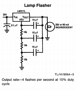
LM317L Lamp Flasher
This one takes the prize for unorthodox use of a linear regulator.
An over-current and over-temperature protected lamp flasher, from the first page of National’s LM317L 1982 datasheet:

This application uses a linear regulator as an inverting amplifier! When ADJ
exceeds (Vout - 1.25V), OUT conducts to (Vin - dropout). When ADJ is less
than (OUT - 1.25V), the regulator “turns off” and OUT ceases to conduct. OUT is
then pulled to GND by the lamp’s filament. The 3-stage RC network provides 180
degrees of phase shift to make the circuit oscillate. Fosc is roughly
predicted by the 3-stage-RC formula: f = 1/(2*pi*R*C*sqrt(6)) - about 0.65Hz.
The schematic claims 4Hz.
Practically, any adjustable - and maybe fixed - regulator could be used. I built this circuit with a standard LM317 and it flashed at about 4.5Hz. Note the lamp is used to pull OUT low when the regulator turns off. A suitable parallel resistance must be used if the lamp is replaced by (e.g.) an LED.
A similar circuit can be spotted on Page 8 of Linear’s LT1038 datasheet. I have traced this circuit back to the LM317L entry in the 1982 National Linear Databook. I cannot imagine where it has been used.
LM317 Tracking Pre-Regulator
A simple way to spread dissipation and tolerate higher Vin-Vout without sacrificing the regulator’s internal protection circuitry. LM117s are shown below, but almost any linear regulator will work. From National’s LM317 datasheet:
![]()
R1 and R2 set the left-hand regulator to maintain Vref*(1 + R2/R1) across the
right-hand regulator. Thus the right-hand regulator’s Vin tracks 5V above its
Vout. This is enough for good regulation and moderate dissipation. The dropout
of the overall design is the sum of the regulator dropouts.
According to National, an LM317 in a TO-3 or TO-220 package with ideal
heatsinking will tolerate Vin-Vout = 12V at max current before hitting
internal protection at approx 20W. Using this design with R2 = 2K2, two LM317s
could provide a max of 24V input-output difference at 1.5A AND provide full
protection. A dual-ganged potentiometer could be cleverly used to divide
dissipation roughly equally across the regulators, for a 1.2V - 20V / 1.5A
adjustable supply.
7800-Series Switching Regulator
See my Linear-Switcher page for details.